@Tuner Boost
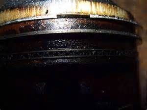
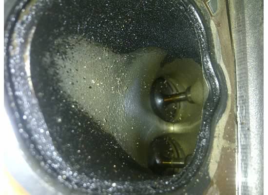
IMHO you and other sources have made a case for the potential problems associated with 'dirty air' intake on DI engines. We can each decide if that's of concern to us and how we might address it.
I'd like to further my technical understanding of improving the quality of PCV via the use of 'catch cans' or other improved systems for separating undesirable oil/oil vapor/water from the intake air stream. If not obvious, my
only interest is application to the 2.0l Ecoboost in the FE.
To that end I've studied info on the Rx Performance website (which presumably is valid for any brand of similar product). I've taken the liberty of downloading and 'altering' a schematic from that website to help with my questions (un-altered and my altered versions of the schematic are attached for reference).
Technical Q's, some which are specific to the Rx Performance product if you are able to answer:
1) Do any or all the "A-B-C" hoses between the engine connections and a catch can need to be sloped toward the catch can to prevent pooling of liquids in the hoses or 'backflow' to the engine? Hose "B" in particular since the PCV valve on the FE may be mounted a lot lower than most that are on the valve cover.
2) Does the "A" hose connection on the engine-end need to be located close to the turbo inlet, or can it be located near the airbox on the airbox outlet pipe (perhaps an easier-to-access location)?
3) What is the role of adding a vented breather (e.g. Rx Performance "Cleanside Separator") to an engine like the 2.0 Ecoboost which has a 'sealed' filler cap with no valve cover breather? Maybe I'm looking at it wrong but lacking a check valve that breather seems to be a vent-to-atmosphere connected to the non-filtered side of the airbox?
4) What's inside the Rx Catch Can (open space? baffles? mesh?) and can it be opened for inspection/cleaning?
5) Are the check valves used in the Rx Catch Can System integral with the catch can fittings, internal to the can or separate external pieces installed inline in the hoses between the can and the engine connection points? As the only 'active' component in the system are they generic replaceable items which can be inspected for correct operation and cleaned?
6) Is it correct that for optimal performance a catch can needs to be installed in a 'cool as possible' location such as in front of the radiator to help facilitate condensation of vapors to liquid in the can?
7) Is there any reason that the drain valve could not/should not be located on the bottom of an extension line remote and below the catch can to facilitate easier access for draining? There's very limited access to the area between the bodywork and the front of the radiator on the FE, making operation of a can-mounted drain valve located there difficult.
TIA, more Q's to follow I'm sure as this nimrod struggles to understand these systems and how they might be implemented on the FE. I really hope you're able to find and document a 2.0 Ecoboost installation for our enlightenment.
![Image]()


